Pneumatic Device Replacement
Low-Cost Opportunity for Methane Abatement
Overview
The replacement of natural-gas driven pneumatic devices represents a meaningful – and when done correctly, relatively low cost – opportunity for reducing methane emissions within the oil and natural gas production industry.
In June 2021, ˛Ężâ±¦µäapp Corporation (˛Ężâ±¦µäapp), the largest producer of natural gas in the United States, announced it was pursuing a full-scale replacement of its over 8,000 natural gas-driven pneumatic devices across its asset base by the end of 2022, with a total projected cost of approximately $20 million. This project alone represents a substantial majority of the methane abatement that is expected to result in ˛Ężâ±¦µäapp’s reducing its methane emissions intensity1 by approximately 65% versus 2018 levels.
Highlighting the important role that replacing natural gas-driven pneumatic devices presents, in November 2021, the U.S. Environmental Protection Agency (EPA) proposed standards that would require subject operators to transition to zero-methane emission pneumatics at new and existing facilities.
The following outlines the work and research conducted by ˛Ężâ±¦µäapp’s Production and Environmental teams to target low-cost opportunities for abating methane emissions from natural gas-driven pneumatic devices.
Background
Pneumatic devices are pervasive in the oil and natural gas production industry, serving as a primary method for managing produced fluids in separators, scrubbers, and filters. For example, ˛Ężâ±¦µäapp has historically used over 8,000 pneumatic devices to regulate gas and liquid separation or to activate safety shutdown devices. A variety of methods, including natural gas, compressed air, nitrogen, or electricity, can be used to power pneumatic devices. The most prevalent methods in the industry are natural gas-driven pneumatic devices, which use pressurized gas to actuate valves and controls and subsequently vent the natural gas once the discrete action is complete.
It is estimated that there are over one million natural gas-driven pneumatic devices currently deployed in the United States oil and gas production sector, and these pneumatics account for over 35% of the sector’s methane emissions. We believe a substantial majority of these emissions are abatable at a relatively low cost
_________________________________________
1Represents Scope 1 methane emissions intensity of ˛Ężâ±¦µäapp’s Production segment for assets owned as of June 30, 2021.

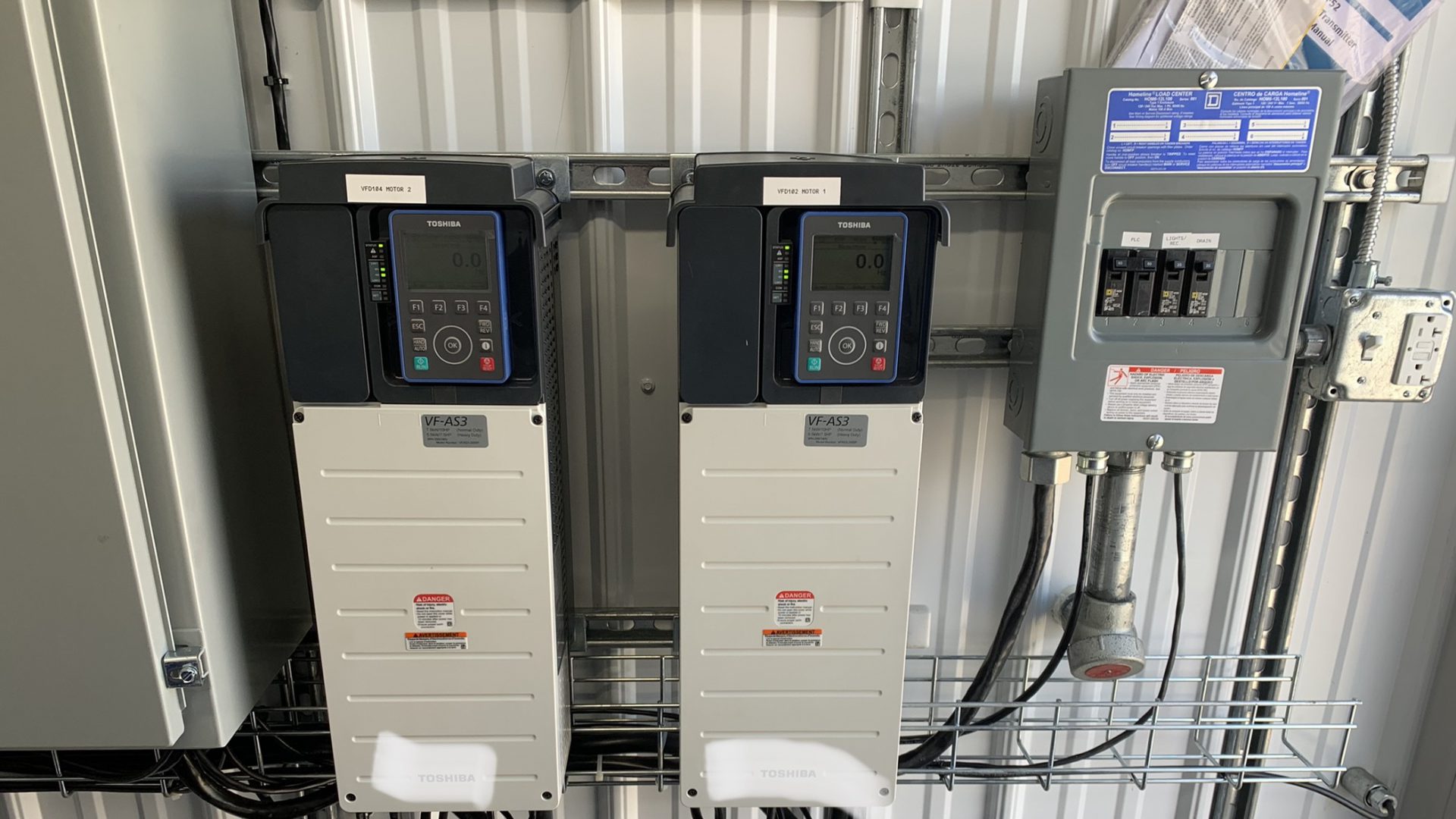
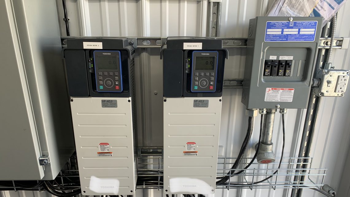
Motor Drives
Motor drives regulate the compressor speed to match the air needs of the pad.
Strategic Rationale for Replacing Natural Gas-Driven Pneumatic Devices
The replacement of natural gas-driven pneumatic devices represents a key strategic opportunity for industrial self-help. It presents one of the highest correlations between action and emissions reduction of all methane emissions abatement opportunities. And it is the most actionable and impactful today: it requires no technological breakthrough, and its results will be felt within the decade.
Using ˛Ężâ±¦µäapp’s program as an example, over the course of two years, the company will have reduced its methane emissions by over 50% principally because of pneumatic replacement. While the methane emissions reduction opportunity and speed and cost with which it can be captured will vary among operators, we believe industry as a whole can make meaningful strides in reducing methane emissions in short order by focusing on natural gas-driven pneumatics.
For most operators, the low cost of a replacement program will translate into a value additive action in a world that ascribes a price to carbon or methane. Using ˛Ężâ±¦µäapp as an example, based on EPA emissions factors and assuming an emissions abatement life (i.e., the period of time for which methane emissions are abated by replacement) of 15 years, pneumatic replacement represented a $3/ton of CO2e project.2
In summary, for many operators, replacing natural gas-driven pneumatic devices will be the quickest, lowest-cost opportunity to meaningfully reduce methane emissions. And meaningfully reducing methane emissions itself represents a key strategic opportunity for the oil and gas industry.
It is important reputationally, demonstrating to our stakeholders that we will act on areas of concern in our collective efforts to address global climate change.
It is important politically, allowing industry to highlight the progress it has made and compare that to sectors that comprise the remaining approximately 70% of domestic methane emissions.
And it is important financially, not only in de-risking long-term demand but also in potentially capturing increased global market share.3
˛Ężâ±¦µäapp’s Pneumatic Replacement Program – Background
The purpose of this white paper is to explain the best practices identified by ˛Ężâ±¦µäapp’s Production and Environmental teams in seeking to replace natural gas-driven pneumatic devices. Over the course of our teams’ analysis of potential solutions, it became apparent that we could both significantly accelerate replacement and limit costs4 versus initial projections by adopting these best practices. We hope that the following can provide similar benefits to your organization.
_________________________________________
2$20 million Ă· (8,000 pneumatics Ă— 51.52 metric tons CO2e per pneumatic per year Ă— 15 years) = $3/metric ton of CO2e
3We are seeing increasing traction in pricing differentiation in both natural gas and oil based on the emissions intensities of operators and operations. At ˛Ężâ±¦µäapp, we believe this trend will only increase. The international community, and in particular Europe, has begun to place a premium on the carbon intensity of imported hydrocarbons. Differentiation between U.S. supply and that of other major producing countries – many of which have nationalized or pseudo-nationalized production with a history of underinvestment in emissions management – will strengthen our competitiveness for global market share.
4Our initial internal projections leveraging primarily electric drives were in excess of $80 million.
Pneumatic Device Inventory – Program Success Depends on Accurate Counts
Quantifying an accurate number of pneumatic devices deployed in the field is critical to the economic and operational success of a large-scale replacement program. Legacy, modified, or non-standard facility designs over a long period of time can add to the challenge of inventorying in-service pneumatic devices. A comprehensive, field-wide engineering review of in-service pneumatic device counts and assumptions is highly recommended as part of the early due diligence phase.
Before large-scale program execution, it is recommended that the operator develop, at minimum, the following procedures:
- Process for high level accounting of the number of low- and high-bleed pneumatic devices per vessel.
- Process for removing from service and decommissioning inactive pneumatic devices and vessels (i.e. oil dump on a three-phase separator for a well only producing natural gas and water). This can be a simple administrative correction / data collection exercise that can have a significant impact on the number of natural gas-driven pneumatic devices to be replaced.
Completing this exercise and gaining accuracy on the overall asset inventory helps enhance engineering analysis, strategy, and budgetary forecasting.
It is also recommended that the operator review and identify potential emissions sources at all locations that are not necessarily associated with pneumatic dumps. These devices are captured as a separate emissions source, but should be factored into the overall emissions reduction strategy. The accurate count will be a significant overall driver for the direction of the replacement program, as it will drive the engineering specifications and design of the alternative pneumatic device as well as the overall cost of the replacement program.
Successful Replacement Campaign
Best Alternative Solutions
With an accurate count of the number of devices utilized at the operator’s facilities and a true understanding of the methane emitted, the operator will be able to make better decisions with a focus on engineering and costs. The next step is determining the best alternative solution to retrofit or replace the pneumatic devices within its asset inventory. Key considerations for identifying alternative solutions are:
- Reliability
- Maintenance
- Power demands (select solutions)
- Meeting the dump rate required for operations
- Cost – initial system cost and ongoing operating expenses
While economics may not be the main driver behind every decision, it should be considered as several alternative pneumatic solutions can be installed at different stages in the life of the well. Overall, the targeted outcome should be a highly coordinated, repeatable, efficient, and scalable replacement program.
As the operator considers alternatives to natural gas-driven pneumatic devices, there are three primary variables that will guide the selection of a solution:
- Pneumatic device counts on the site
- Produced liquid volumes (equates to number of dump cycles)
- Ancillary pneumatic devices (such as pumps and blow cases)
˛Ężâ±¦µäapp has identified three alternatives to its natural gas-driven pneumatic devices: Compressed Air, Nitrogen, and Electric Drives.

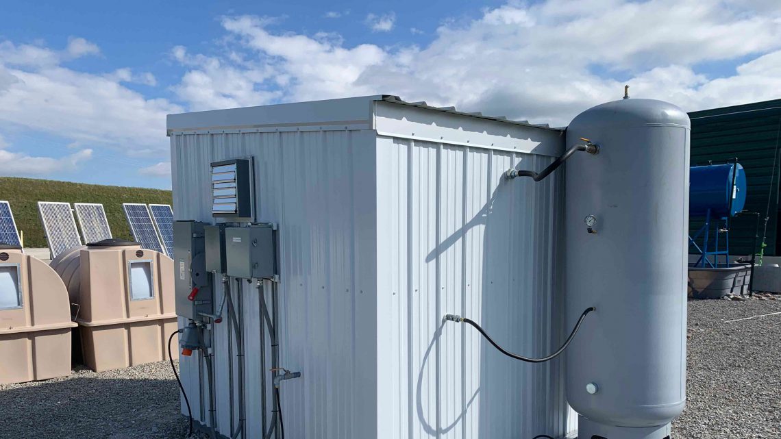
Compressed Air System
The compressed air system is housed in a shed, which helps prevent freezing in the winter.
COMPRESSED AIR
Compressed air systems utilize dried air to power pneumatic devices instead of natural gas, eliminating the methane emissions that would otherwise be generated when the device vents. The compressed air system requires a robust power source, gas dryer, volume tank, and filter, which can lead to the overall initial cost being significantly higher than other options.
Compressed air is typically used for locations with high pneumatic device count pads due to the high instrument air volume and power demands. Although initial system cost is high, the replacement cost per pneumatic device is lower on these locations because all devices are air actuated. At ˛Ężâ±¦µäapp, sites with 24 or more pneumatic devices and high produced liquid volume are candidates for a compressed air system.
Available power supply to each site also is an important consideration. For remote sites, the power generation system must be capable of operating the air compressor, site electronics, and controls. In some instances, existing power generation may meet these requirements. For sites that have access to commercial power, initial system costs can be reduced by 50% per facility due to not having to purchase power generation.
˛Ężâ±¦µäapp evaluated three compressor types for compressed air systems – scroll, screw, and reciprocating. Each of these technologies has unique ideal run conditions, expected run life, and maintenance expenses (OPEX). Operators should explore all three technologies to determine which is best for their specific application and program. ˛Ężâ±¦µäapp’s preferred compressor type is the reciprocating compressor, as it has a higher discharge pressure to provide additional stored air volume, can run intermittently, has high efficiency, lower initial cost, and minimally invasive maintenance.
The following pros and cons should be considered when selecting compressed air as the pneumatic device replacement solution:
- Pros
- Inert air
- Removal of freezing issues with sufficient air dryer design
- Minimal maintenance costs
- Cons
- High initial capital cost ($60K-$110K, depending on power supply needs)
- Single failure point with loss of compression
- Hazards associated with introducing oxygen into part of the process stream
NITROGEN
Nitrogen provides a feasible alternative to operating pneumatic devices when power is not available to run air compressors, or actuators are not capable of going fully electronic. There are several methods of supplying nitrogen to pneumatic devices: compressed cylinders, bulk nitrogen trucks, and MicroBulk.
While utilizing nitrogen has a lower initial capital cost than compressed air or electric drives, it may have a higher long-term operational expense due to the need for regular replenishment of nitrogen to the site. The low initial cost makes nitrogen an attractive option in many scenarios, but overall is recommended for pads with two combinations of liquid production rate and pneumatic device count:
- Nitrogen Candidate A: 0-10 Barrels of fluid per day (entire pad production) with no consideration for number of pneumatic devices.
- Nitrogen Candidate B: 10–50 Barrels of fluid per day (entire pad production) with less than 24 pneumatic devices on the pad.
The following pros and cons should be considered when selecting nitrogen as the pneumatic device replacement solution:
- Pros
- Inert gas
- Removal of freezing issues
- Less nitrogen replenishment for smaller pads
- Low initial capital cost <$20,000
- Little to no maintenance
- Cons
- Hazardous in confined space
- Monthly operating expense – up to $1,500/month (depending on nitrogen consumption)
- Regular nitrogen replenishment required
- Continuous low rate nitrogen flash loss when using liquid nitrogen in addition to vent loss
ELECTRIC DRIVEN ACTUATION
Electric-drive systems provide multiple advantages for reliability, remote monitoring, and operation of the dump valve. These systems leverage the use of small electrical motors to operate actuators attached to control valves. Electric drives can be installed with a new valve or mounted independently onto a preexisting valve to retrofit a pneumatic drive. The additional advantage of these electric actuators is that they can be integrated into existing controls to allow for remote operations such as throttling production rates in response to downstream pressure fluctuations. The disadvantage of these systems is the overall expense is relatively high and very linear with the number of pneumatics on the facility (as the number of pneumatic devices increases, so does the overall cost). Overall, it is recommended that electric-drive actuators be installed on pads with a reduced valve count and higher production.
- Electric Driven Actuation Candidate: Greater than 50 Barrels of fluid per day (entire pad production) with less than 24 pneumatic devices on the pad.
Wells in the early life of production are typically strong candidates for electric drive systems. Additionally, internal data shows that a well’s actual pneumatic methane emissions are highest during the first 12-18 months of production due to more frequent device actuations as result of higher liquid volumes. As a result, ˛Ężâ±¦µäapp has made it a best practice to install electric-drive systems on equipment for all new well developments.
The following pros and cons should be considered when selecting electric-driven actuation as the pneumatic device replacement solution:
- Pros
- Leverage valves that are in place
- Increased control point
- Throttling production capability
- Lower maintenance cost
- Cons
- Increased cost
- Power consumption
- Cross functional team for upsets
Solution Comparison
A thorough economic comparison should be completed for all scenarios prior to securing project funding. Since nearly all facilities are unique, a per-location determination is recommended and will likely point toward a mix of some or all the methods detailed above. Locations can be “bucketed” into groupings that share similar characteristics to analyze dozens of locations in a relatively short period of time.
An example of location “buckets” includes:
- Wet gas (condensate) facilities
- Conducive to compressed air or nitrogen alternatives from calculated GHG emissions due to condensate flash and other fugitive emissions as well as large quantity of pneumatic devices required for condensate facilities and processing.
- Low well count, dry gas facilities (no dehydration or other ancillary equipment)
- Favorable to electric-drive actuators due to low pneumatic device count and limited rework.
- High well count, dry gas facilities (with dehydration or other ancillary equipment)
- Favorable to compressed air or nitrogen systems due to high volume of pneumatic devices on location simply due to total well count (scalable), plus emissions control equipment typically installed for dehydration systems and other ancillary equipment.
Table 1 provides a high-level summary of the operating parameters for each solution.

